
Floating head heat exchanger is one type of heat exchanger and a common chemical equipment. To understand its working condition, it is necessary to understand its principle and basic characteristics of the equipment at the first, and then understand its operating conditions.
Overview of heat exchange equipment
Heat exchange equipment is a device used for the transfer of heat or enthalpy between two or more fluids, between one fluid and one solid, between solid particles or thermal contact, or between the same fluid at different temperatures.
According to the principle of heat transfer or heat transfer methods, it can be classified into direct heat exchangers, regenerative heat exchangers, surface heat exchangers, and intermediate heat exchangers. Surface heat exchangers are further divided into tube type heat exchangers, plate type heat exchangers, and other forms of heat exchangers. Floating head heat exchanger belongs to a type of shell and tube heat exchanger.
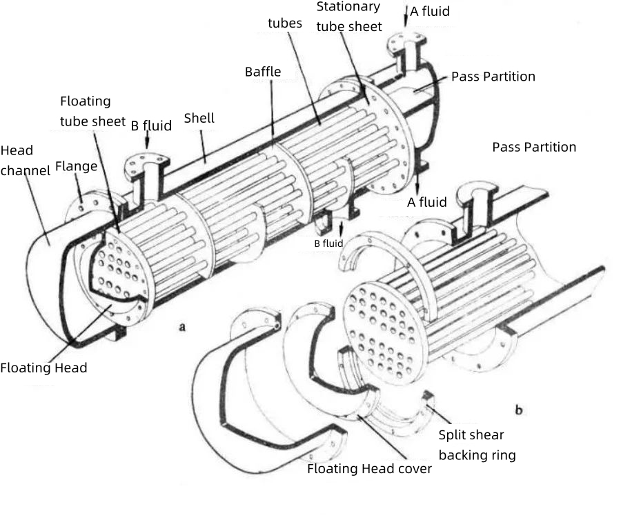
Floating head heat exchanger: Only one end of the tube sheets at both ends is fixed to the shell, and the other end can move freely relative to the shell, which is called a floating head. The float head is composed of a floating tube sheet, split shear backing ring, and a floating head cover, which are detachable connections, and the tube bundle can be extracted from the shell. The thermal deformation of the tube bundle and the shell are not mutually constrained, thus no thermal stress is generated. Its advantage is convenient cleaning between and inside pipes, without generating thermal stress. But its structure is complex, the cost is higher than that of fixed tube sheet heat exchangers, the equipment is bulky, the material consumption is high, and the small cover at the floating head end cannot be inspected during operation, resulting in high sealing requirements during manufacturing. Suitable for situations where the wall temperature difference between the shell and the tube bundle is large or the shell side medium is prone to scaling.
Structure of Floating Head Heat Exchanger
Each time the fluid passes through the shell is called a shell side. Each passage through the bundle is called a tube side.
1. Shell side
1.1 Cylinder body
The cylinder provides the required pressure space for the process and is one of the main pressure components of pressure vessels. The cylindrical cylinder is the most commonly used cylinder structure in engineering. The shell design can be made of seamless steel pipes or rolled from steel plates. In actual production, the form of steel plate coil welding is more widely used. During the processing, attention should be paid to avoiding the intersection of circumferential and longitudinal welds.
There are various forms of materials used for processing cylinder bodies, among which low alloy steel accounts for a large proportion in production due to its excellent performance. Q345R is a specialized steel plate for pressure vessels with a yield strength of 340MPa. It is the most widely used and experienced steel plate in China's pressure vessel industry, mainly used in the manufacturing of medium and low pressure vessels. Q345R steel plate, as a processing material for other parts such as the heat exchanger cylinder, not only ensures structural requirements but also reduces manufacturing costs.
There is a connecting pipe welded on the cylinder wall for the inlet and outlet of the shell side fluid. To prevent direct impact of imported fluid on the tube bundle, which may cause erosion and vibration of the tube, anti impact baffles are often installed at the inlet connection of the shell side.
1.2 Shell cover
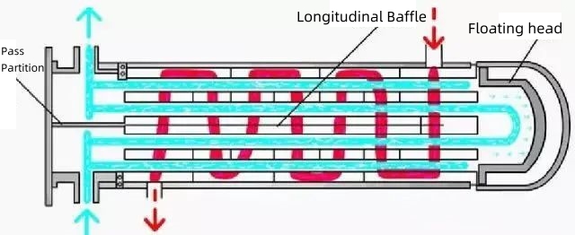
The shell cover is located at the rear end of the heat exchanger, equivalent to a rear channel. It uses a floating head to separate the fluid on the tube side and shell side. The outer part of the floating head changes the flow direction of the fluid on the shell side, while the inner part changes the flow direction of the fluid on the tube side. The cylinder of the shell cover is usually 100mm larger than the inner diameter of the heat exchanger cylinder.
The shell cover is connected to the heat exchanger through flange bolts, but due to the different inner diameters of the two cylinders, a standard flange can only be used on the side with the larger inner diameter, while a matching non-standard flange can be used on the other side. This is to ensure the strength and stiffness of the connection.
1.3 Baffles
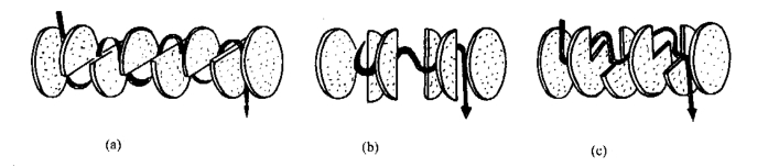
The purpose of setting baffle plates is to increase the flow velocity of the shell side fluid, increase turbulence, and make the shell side fluid vertically flush the tube bundle to improve heat transfer, increase the heat transfer coefficient of the shell side fluid, and reduce scaling. In a horizontal heat exchanger, the baffle plate also serves as a support for the tube bundle. The commonly used baffle is divided into two forms: bow-shape and disc-shape. Baffles are generally evenly spaced, and the baffle plates at both ends of the tube bundle should be as close as possible to the inlet and outlet connections of the shell side medium.
2. Tube side
2.1 Channel
Located at the front end of the heat exchanger, it evenly distributes the fluid transported from the pipeline to each heat exchange tube, and collect the fluid inside the tube and send it out of the heat exchanger. The inner diameter of the front head channel cylinder is the same as that of the heat exchanger cylinder, and the design pressure is the design pressure of the tube side. Horizontal layered partitions are installed inside the channel.
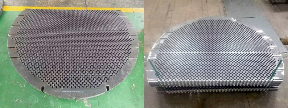
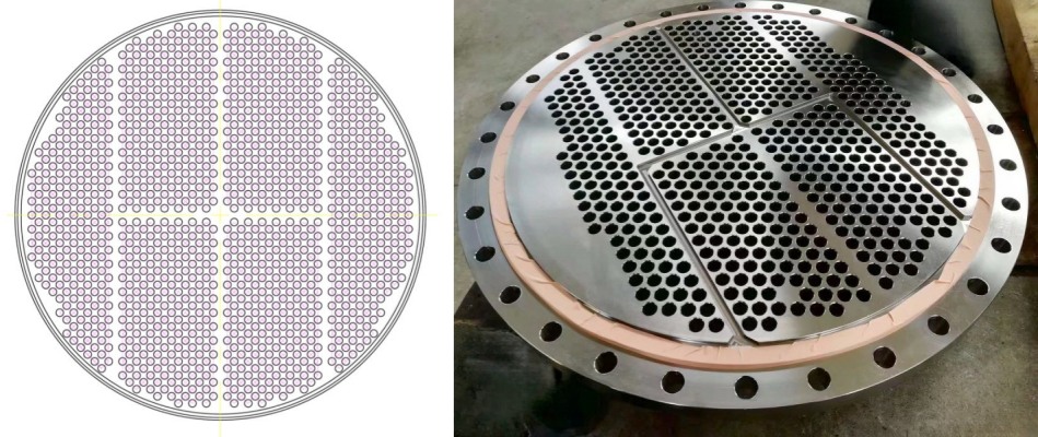
2.2 Tube sheet
One of the most important components of shell and tube heat exchangers. Used to arrange heat exchange tubes, separating the fluid between the tube side and shell side, while being affected by the combined pressure and temperature of the tube side and shell side. For floating head heat exchangers, the fixed tube sheet at the front end is clamped by the front head channel and cylinder, and is fixed by bolts. The floating tube sheet at the rear is clamped by a floating head and a split shear backing ring and fixed by flange bolts. In this way, when the heat exchange tube deforms due to thermal expansion, one side of the floating tube sheet can move freely inside the rear channel without generating thermal stress.
2.3 Heat exchange tubes
A partition wall used to separate fluids and exchange heat. The commonly used materials for heat exchange tubes include carbon steel, low alloy steel, stainless steel, copper, aluminum alloy, etc.
The connection between heat exchange tubes and tube sheets is one of the most critical technologies in the design and manufacturing of shell and tube heat exchangers, and is the location with the highest accident rate. The connection method mainly involves a combination of expansion joint, welding, and welded and expanded. (know more please click here Connection method of heat exchange tube and tube sheet)
2.4 Floating head and Split Back Ring
The most distinctive feature of a floating head heat exchanger is reflected in the floating head. The floating head drives the free expansion and contraction of the heat exchange tube, thereby eliminating thermal stress. The floating head is matched with a floating head cover and a split back ring to "clamp" the floating tube sheet and complete the work.
The floating head cover consists of a floating head flange and a spherically dished head. The aplit back ring plays an important role in ensuring the sealing of the floating head end and preventing leakage between media. Hooks and rings are generally of a split type structure, requiring reliable sealing, simple and compact structure, and easy manufacturing and disassembly.
Advantages of Floating Head Heat Exchangers
3.1 The floating head heat exchanger tube can be pulled out for convenient and quick cleaning of the tube and shell side.
3.2 The temperature difference between the media of the floating head heat exchanger is not limited.
3.3 Floating head heat exchangers can operate under continuous high temperature and ultra-high pressure. Generally, the ambient temperature should be less than or equal to 450 degrees, and the working pressure should be less than or equal to 6.4Mpa.
3.4 Floating head heat exchangers can be used in places with severe scaling.
3.5 Floating head heat exchangers can be used in areas where the tube side is prone to corrosion.


 IPv6 Network Supported