
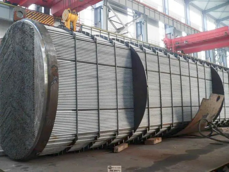
A U-tube heat exchanger refers to a shell and tube heat exchanger where the tube bundle consists of U tubes with varying bending radii, and both ends of the tubes are fixed on the same tube sheet. Since each U tube can move freely, there is no temperature difference stress generated between the tube bundle and the shell. Baffles and longitudinal baffles are installed inside the shell side. The baffles are fixed by tie rods, while the longitudinal baffles are rectangular plates installed parallel to the direction of the heat transfer tubes to increase the velocity of the shell-side fluid. Its structure is more complex than the fixed tube plate heat exchanger and simpler than the floating head heat exchanger.
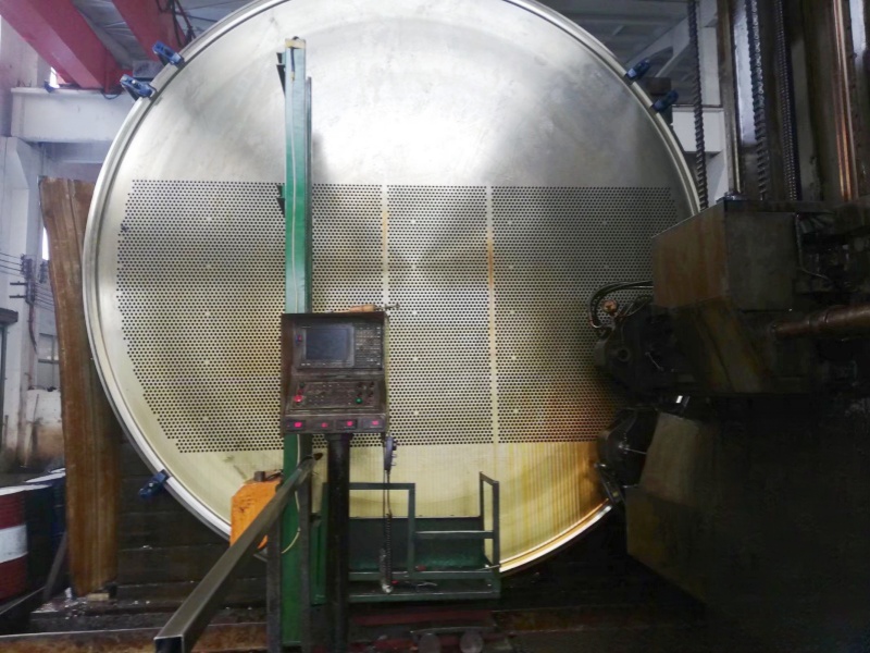
The advantage of the U-tube heat exchanger is that the free floating tail part solves the problem of temperature difference stress and can be core-pulled for cleaning. It is also a heat exchanger that can be used for high temperature, high pressure and high temperature difference, so it is widely used in the petrochemical industry. The commonly used structure for connecting the tube bundle and shell of a U-tube heat exchanger is to sandwich one tube sheet between two girth flanges. In this structure, the forces exerted by the bolts on the flanges on both sides of the tube plate are equal. The design of the bolts should take both sides of the tube sheet into consideration and be designed with a larger bolt load. In the operating state, the bolt force is equal to the gasket pressing force plus the axial force caused by the medium pressure. The axial force on the high-pressure side is large, resulting in a smaller clamping force on the gasket, while the opposite is true for the low-pressure side. Assuming the bolts are tightened in the operating state, the sealing requirements are first met on the low-pressure side. When there is a large pressure difference between the two sides, if the sealing requirements are not yet met on the high-pressure side, the gasket on the low-pressure side may have been crushed, resulting in potential leakage.
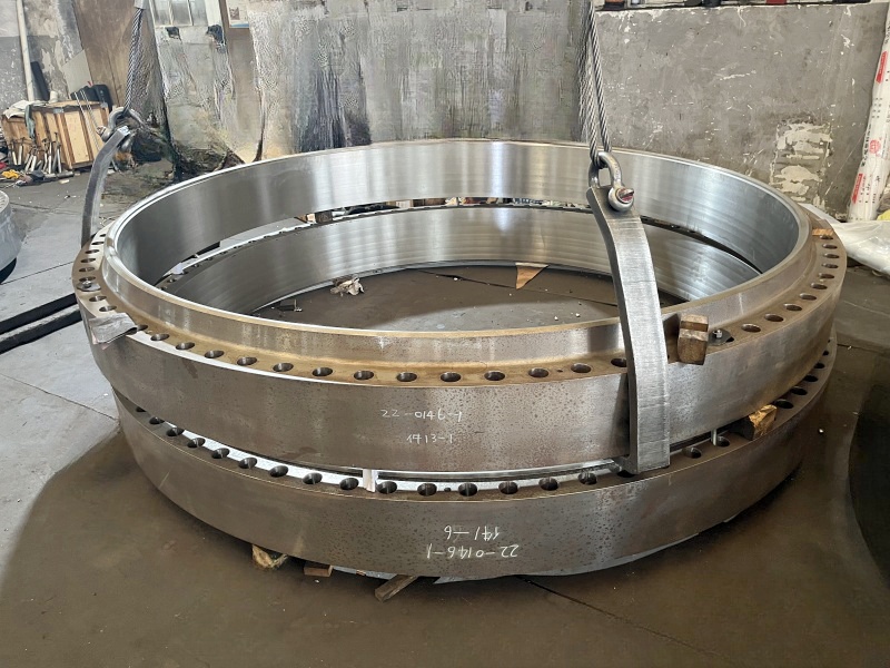
In order to solve the sealing problem of the U-tube heat exchanger under large pressure difference conditions, bolt holes with raised seats can be added on the extended portion of the tube sheet. The bolts, gaskets, and flanges can be designed separately according to the requirements of each side. The thickness of the extended portion should meet the bolt force requirement for sealing on the high-pressure side. During the pre-tightening process, the high-pressure side should be sealed first before sealing the low-pressure side. Another approach is to connect the two flanges and the tube sheet using fully threaded studs. The extended portion of the tube sheet is machined with internal threads, with a thickness equal to 1.5 times the diameter of the stud. The extended portion of the tube sheet should be positioned closer to the high-pressure side. Bolt holes and threaded holes are created on the extended portion of the tube sheet to connect the flange on the high-pressure side and the flange on the low-pressure side, respectively. A standard flange can be used on the low-pressure side. In engineering practice, process requirements, temperature and other factors should also be taken into consideration before making a decision.


 IPv6 Network Supported