
With the integration and large-scale development of petroleum refining equipment in China, the size specifications of the reactor tube sheet forgings are constantly increasing. The diameter of the epoxy ethane reactor tube sheet in a petrochemical project has exceeded the limit of the company's 185MN hydraulic press equipment (7.5m). When the diameter of the tube sheet is smaller than the opening size of the press, the commonly used method is to control the entry of the anvil by rotary forging from the outside to inside; When the diameter of the tube sheet exceeds the opening size of the press, if it is formed by stepwise spinning from the outside to the inside, when the diameter of the billet is greater than 7.5m, the central area of the billet cannot move to the bottom of the hammer anvil, resulting in steps in the central area, increasing process weight and manufacturing costs. Therefore, the industry usually adopts the technical route of segmented forging and splicing welding for forming. However, segmented forging often adopts the envelope method for forming, which generates a large amount of forging allowance, resulting in a large amount of waste of raw materials, and welding forming is also not conducive to ensuring the overall internal quality. This article systematically studies the overall forging process scheme of extra large tube sheets based on the dimensional characteristics of the outer dimensions. It breaks through the limitation of 185MN hydraulic press equipment on the forging of 7.8m extra large tube sheets, ensuring quality while reducing manufacturing costs.
1.Forging information
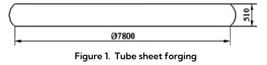
The material of the epoxy ethane reactor tube plate for a certain project is SA765. Gr.2, with a diameter of 7.8m and a forging weight of 200.3t. Please refer to Figure 1 for the specific forging diagram. Ultrasonic testing shall be carried out in accordance with NB/T47013.3-2015, with acceptance requirements of Level I for important areas within 200mm of the outer circle of the tube sheet, and Level II for other areas.
Discussion on Integral Forging Technology Scheme
2.1 Advantages of Integral Forging Scheme
Compared with segmented forging and welding forming, the advantages of integral forging forming of extra large tube sheets are as follows:
(1)By using integral forging, the shape of the forging is close to the size of the finished product and requires less materials. However, by using the segmented forging welding forming method, a large amount of excess is removed during machining of the rough forging, resulting in serious material waste and not in line with the concept of green manufacturing;
(2) By using integral forging, the metal flow line is complete, the organization is uniform, and the mechanical performance indicators are stable. However, by using welding forming, each part is forged into a rectangular cross-section panel through the envelope method, and then processed into a circular or arc-shaped plate, which destroys the metal flow line;
(3) The use of integral forging only requires a vertical lathe to complete mechanical processing, with a short processing cycle. The method of welding and forming requires the cooperation of a milling machine and a vertical lathe to complete mechanical processing, resulting in a long processing cycle;
(4) The use of welding forming method results in a long welding cycle due to the thicker thickness of the tube sheet, longer welding seams, and larger welding workload. Moreover, welding stress can cause deformation of large tube sheets, affecting the subsequent drilling process of tube sheets and not conducive to ensuring the quality of forgings.
2.2 Proposal of Integral Forging Forming Scheme
The diameter of the tube sheet forging process is 7.8m. After the actual forging is completed, the outer circle of the blank forging takes on a "bulge" shape. With the bulge added, the maximum contour of the outer circle of the tube sheet is close to 8.0m, exceeding the opening limit of the 185MN oil press (7.5m), and cannot be formed according to the traditional spinning scheme. Based on the actual size of the tube sheet and the forging process, a new step-by-step zoning and different spinning control scheme for different stages is proposed:
(1) When the diameter of the billet is small (less than 6.5m), the traditional spinning scheme is still used, gradually spinning from the outside to the inside.
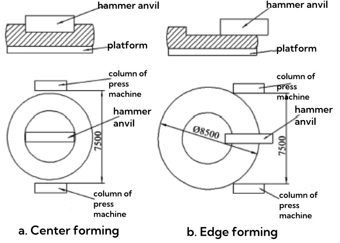
(2) When the diameter of the billet is large (greater than 6.5m), use an upper hammer anvil and a lower platform to first use a hammer to spin and shape the central area, as shown in Figure 2 (a). After forging, the center is in a groove shape (the outer diameter of the tube sheet does not exceed the opening of the press), and then move the tube sheet billet as a whole outward, as shown in Figure 2 (b). The edge area is moved directly below the hammer anvil to achieve the spinning and forming of the edge. This method can break through the limitation of opening the crotch of the press. With a crotch opening of 7.5m and without adding fixtures, a super large forged tube sheet with an outer diameter contour close to 8.5m can be formed.
2.3 Discussion on Integral Forging Process Parameters
The tube sheet belongs to cake shaped forgings, and the non-destructive testing requirements for this extra large tube sheet are relatively high. In order to ensure the compaction effect of the center and avoid the occurrence of cake shaped forgings with flaky defects, combined with the forming characteristics of cake shaped forgings, an overall process plan design is carried out:
(1) First, pre elongate the steel ingot, cut off 6% of the nozzle and 24% of the riser, and remove materials with poor quality at the beginning and end of the ingot;
(2) Pre upsetting of the billet, with a deformation of 40% to 50%, and controlling the ratio of billet diameter to height D/H between 1.2 and 1.3, can compact defects such as porosity, welding voids, and micro cracks in the center of the steel ingot through high temperature and large deformation during upsetting;
(3) According to the traditional control anvil method, the anvil is sequentially spun from the outside to the inside until the D/H is between 2.8-3.3. The ratio of the anvil width W (anvil amount) to the billet height H is controlled between 0.5-1.0, and the deformation amount is 10-15%. This can avoid the rigid sliding tearing effect (RST effect) causing cracks, and can disperse inclusions, improve the distribution of inclusions inside the billet, and prevent the formation of large-sized sheet-like inclusions;
(4) Roll forging of the outer circle, with a rolling amount of 15% to 20%, causes the material to flow axially through radial deformation, resulting in a change in the morphology of sheet-like inclusions and a significant reduction in size;
(5) Continue to use the controlled anvil method to gradually rotate from the outside to the inside, with a height of 730-800mm (diameter 6500-6300mm), and reserve 30% -35% deformation for subsequent firing;
(6) Using a hammer anvil for step-by-step zone spinning at the center and edge, the diameter of the center pressing groove is determined by the length of the hammer anvil. The longer the hammer anvil, the larger the groove diameter, and the greater the forming force during center spinning; If the length of the hammer anvil is short and the groove diameter is too small, the forming force is small when spinning the center, but it is difficult to form when pressing the edge. Therefore, the preset groove diameter is about half of the tube sheet diameter, about 400mm.
3. Numerical simulation analysis of the key process of integral forging
The traditional outward inward spinning forming scheme has mature process parameter control. This simulation only focuses on the key process of first spinning the center and then spinning the edge, studying the influence of hammer and anvil width and pressing amount on the forming quality and forming force of the tube sheet, and determining the optimal process parameters such as hammer and anvil width and pressing amount per pass.
3.1 Simulation parameter settings
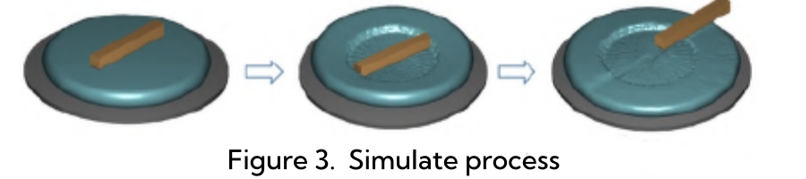
The simulation software uses Forge, with a billet size of ∅6450mm x 750mm and a mesh number of 177000. The contact surface between the billet and the upper and lower molds is Coulomb friction, with a friction factor of 0.3. The initial forging temperature of the billet is 1200℃ and the pressing rate is 10mm/s. The simulation process is shown in Figure 3. First, perform center spinning with a groove depth of 240mm, and then perform edge spinning. In order to ensure the uniformity of deformation and improve forming efficiency, the simulation process uses a full anvil as the first hammer for both center and edge spinning forming.
3.2 Impact of Hammer Anvil Width on Forming Quality
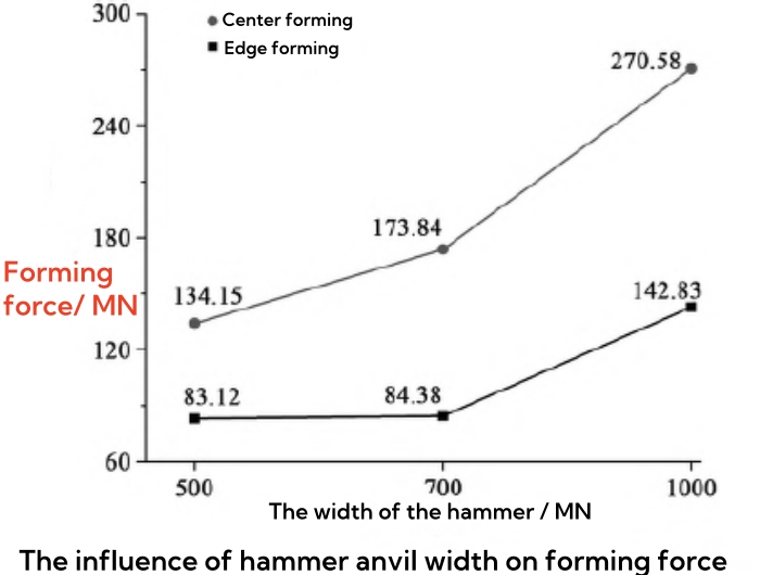
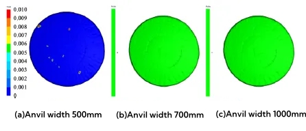
To study the effect of hammer and anvil width on forming quality, the simulation scheme is as follows: hammer and anvil length 4000mm, working face edge chamfer R100mm, pressing amount 120mm (pressing twice), hammer and anvil width 500mm, 700mm, and 1000mm respectively.
(1) The influence of hammer anvil width on forming force: The influence of the width of the hammer and anvil on the forming force is shown in Figure 4. During the center forming and edge forming processes, the forming force increases significantly with the increase of the width of the hammer and anvil. Moreover, due to the larger contact area between the hammer and anvil and the billet during center forming, the center forming pressure is much greater than the edge forming pressure. When the width of the hammer anvil is 500mm and the center forming force is 134.15MN; When the width of the hammer anvil is 700mm and the center forming force is 173.84MN, it is close to the forging limit of the press; When the width of the hammer anvil is 1000mm and the center forming force is 270.58MN, it exceeds the forging limit of the 185MN press.
(2) The influence of hammer anvil width on folding damage: As shown in Figure 5, when the width of the hammer anvil is 500mm, surface folding occurs, as shown in Figure 5 (a); When the width of the hammer and anvil is 700mm and 1000mm, the surface quality is good and no folding occurs, as shown in Figures 5 (b) and (c), indicating that the anvil width has a significant impact on folding. To avoid folding, a larger hammer and anvil width should be selected.
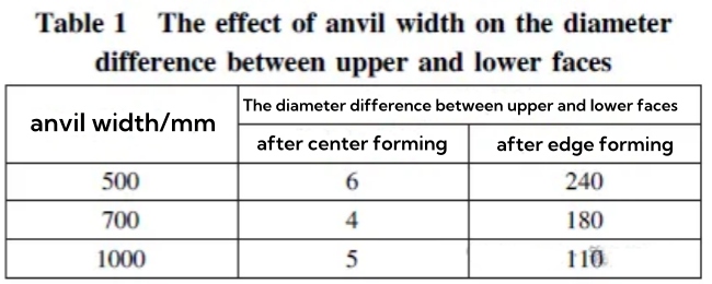
3) The influence of hammer anvil width on the diameter difference between the upper and lower end faces: Due to the small contact area between the hammer anvil and the billet during the spinning process, while the contact area between the billet and the lower platform is large, the forming results in a larger upper end face diameter and a smaller lower end face diameter. The influence of the width of the hammer anvil on the diameter difference between the upper and lower end faces is shown in Table 1. After the center is formed, the diameter difference between the upper and lower end faces is very small, indicating that the diameters of the upper and lower end faces are basically the same; After the edge is formed, as the width of the hammer and anvil increases, the diameter difference between the upper and lower end faces gradually decreases.
3.3 Impact of reduction on forming quality
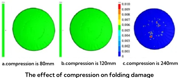
To study the effect of pressing amount on forming quality, the simulation scheme is as follows: the length of the hammer anvil is 4000mm, the width of the hammer anvil is 700mm, the chamfer of the working surface edge is R100mm, and the pressing amount is 80mm (pressing three times), 120mm (pressing two times), and 240mm (pressing one time), respectively.
(1) The effect of compression on folding damage:
The effect of compression on folding damage is shown in Figure 6. When the compression is 80mm and 120mm, no folding occurs on the surface, as shown in Figures 6 (a) and (b). When the compression is 240mm, folding occurs on the surface, as shown in Figure 6 (c), indicating that the greater the compression, the greater the tendency to fold.
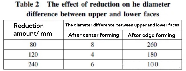
2) The influence of reduction on the diameter difference between the upper and lower end faces
The influence of reduction on the diameter difference between the upper and lower end faces is shown in Table 2. After center forming, the diameter difference between the upper and lower end faces is very small, and the diameters of the upper and lower end faces are basically the same; After edge forming, as the amount of pressing increases, the diameter difference between the upper and lower end faces gradually decreases.
3.4 Numerical simulation conclusions
According to the above simulation results, it can be seen that the larger the width of the hammer and anvil, the smaller the tendency of folding and the smaller the difference in diameter between the upper and lower end faces. When the width of the hammer and anvil is 700mm, the forming force is close to the limit of the 185MN hydraulic press equipment. Therefore, it is more reasonable to choose a width of 700mm for the hammer and anvil.
Based on the influence of the pressing amount on the diameter difference and folding of the upper and lower end faces, it is more reasonable to choose 120mm (pressing twice) as the pressing amount. According to the simulation of a hammer anvil with a width of 700mm and a reduction of 120mm, the difference in diameter between the upper and lower end faces is 180mm. In order to reduce the impact of this problem on the forming quality, the billet is not flipped during the spinning process before pressing the groove, so that one end of the billet has a larger diameter and the other end has a smaller diameter (control the diameter difference to be around 180mm). When pressing the groove, the small end of the billet is facing upwards, and after center forming and edge forming, the diameter of the upper and lower end faces is basically the same.
4. Integral forging process plan and production verification
Based on the above analysis and numerical simulation results, develop a forging process plan:
(1) In the first round, the steel ingot is pre drawn and cut, with 6% of the nozzle and 24% of the riser cut off;
(2) For the second heat, the billet is upset to H=2800mm, and the height is spun to H=1500mm using the controlled anvil method. The amount of anvil feed W/H is 0.5, and the amount of compression is 12%;
(3) Third heat, roll forging outer circle, roll forging amount of 20%, flat end face;
(4) For the fourth round, continue to use the control anvil method to spin the height to H=750mm, with an anvil amount of W/H of about 0.5 and a pressing amount of 15%. During the spinning process, do not flip the surface and control the difference in diameter between the upper and lower parts to about 180mm;
(5) In the fifth heat, with the small end of the billet diameter facing upwards, use a 700mm wide hammer and anvil to press the central area in two passes to H=510mm, with a pressing amount of 120mm. Then move the edge area of the billet below the press hammer and anvil, and press the height to H=510mm in two passes, with a pressing amount of 120mm.
The actual forging process is shown in Figure 7, with good surface quality of the blank and dimensions that meet the processing requirements of the tube plate. After the surface of the tube plate is exposed to light, ultrasonic testing is qualified. Through practical production examples, it is demonstrated that this method can break through the limitation of opening the crotch of a 185MN oil press and complete the overall forging of a large tube plate with a diameter of 7.8m without increasing the number of fixtures.

Conclusion
(1) The integral forging process scheme of using step-by-step zoning and different stages and spinning control for the 7.8m diameter ultra large tube sheet is feasible. This method can break through the limit of 7.5m opening of the 185MN oil press.
(2) Through numerical simulation research, under the same compression amount (120mm), the larger the width of the hammer and anvil, the greater the forming force, the smaller the difference in diameter between the upper and lower end faces, and the smaller the tendency to fold; Under the same hammer anvil width (700mm), the greater the amount of pressing, the smaller the difference in diameter between the upper and lower end faces, and the greater the tendency to fold.
(3) Based on the numerical simulation results and combined with the pressure limit of the 185MN hydraulic press, it is determined that the reasonable hammer anvil width and pressing amount for the center and edge forming of this specification of tube sheet are 700mm and 120mm (pressing twice).
Wuxi Changrun has provided high-quality tube sheets, nozzles, flanges, and customized forgings for heat exchangers, boilers, pressure vessels, etc. to many well-known petrochemical enterprises at home and abroad. Our customers include PetroChina, Sinopec, Chevron, Bayer, Shell, BASF, etc. Send your drawings to sales@wuxichangrun.com We will provide you with the best quotation and the highest quality products.


 IPv6 Network Supported